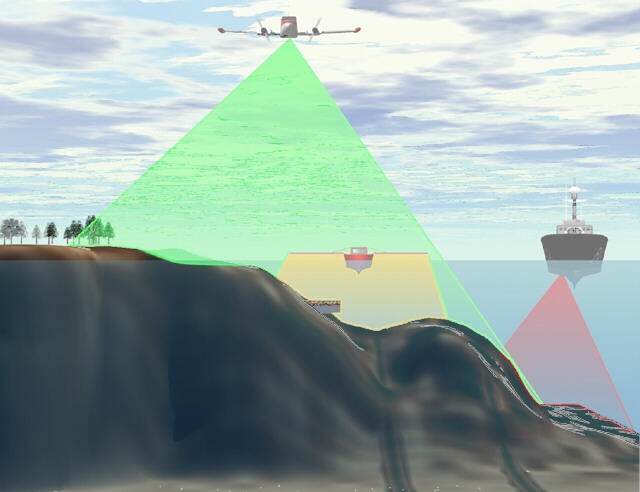
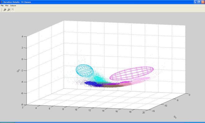
Multibeam backscatter is the reflectivity measurement, where as the sidescan sonar imagery is the actual intensity of the return signal. The Sidescan sonar towing configuration provides greater maneuverability, as the depth of the tow-fish above the seafloor can be adjusted, in view of the swath width. For example, the sidescan imagery is less prone to be affected by the slope of the seafloor as it can be positioned, where as the multibeam can only receive the backscatter intensity as it reaches the survey vessel.
The footprint size at the outer beam of the sidescan sonar is larger than at the nadir beam as slant range is greater in the far range; subsequently increasing the two way travel time of the acoustic signal. A larger footprint has a greater uncertainty of detecting the first return, as well as a lower resolution. Hence, the theoretical maximum speed at which the survey vessel should go can be calculated, to ensure not only 100% coverage of the along track beam footprint, but also optimize the footprint size for all the beams. Therefore speed is an important factor to consider when planning a survey.
Thus practically, gaps in the multibeam data sets are present if the survey speed is too fast, as the vessel would have moved away before the acoustic return can reach the receiver. On the other hand, multibeam surveying uses expensive resources, such as ship fuel and a very slow survey speed would use the resources with a limited efficiency, resulting in a smaller area ensonified in the survey. Additional effects are also present for the sidescan sonar as the system comprises of a towed fish. Slow speeds may result in the fish having a decreased momentum/tension in the cable, changing the position of the fish relative to the vessel.
The difference between multibeam positioning and the sidescan sonar positioning is that the sidescan towed fish is found behind the ship, and hence this needs to be corrected for, in relation to the on board DGPS navigation system. This can be done most simply by doing trigonometric calculations, based on the length of the cable out (lay back) and the depth of the fish above the seafloor, as well as accounting for the heading. Base line acoustic positioning systems may also be used, with an acoustic signal being sent by the fish to the vessel, or by triangulation with transducers being based on the seafloor. Similarly the position of the multibeam transducer and receiver on the vessel also needs to be added to a vessel configuration file during processing. Furthermore, a time-lag correction needs to be applied, ensuring the correct position is recorded, with synchronized times of the navigation and the satellite.
If a survey was taken at another time of the year then different weather conditions affecting the movement of the survey vessel in the x,y and z directions would be recorded in the raw data acquired. Hence, attitude sensors on the vessel need to be used to correct the data to different types of movement, or the roll, pitch, heave and yaw. The pitch is a measure of the rotation of the survey vessel in the x axis; the roll is the rotation in the y axis and heave in the z axis. The yaw is the offset between the survey lines. A consequence of more turbulent weather conditions, which has a greater impact on the sidescan system, is the increased presence of air bubbles. This affects the way sound propagates in the surface mixed layer and hence can cause artefacts in the data. Bubbles may also originate from the propellers of other vessels which may be present at other times of survey.
The sea floor composition and the angle of incidence primarily cause variation in backscatter intensity, according to Lambert’s law. The roughness and hardness or acoustic impedance of the sea floor are two key parameters which vary with geological and biological characteristics. These parameters have varying contributions to the backscatter intensity, depending on the angle of incidence. Hence the energy of the ping which is reflected or absorbed is affected by the sediment geotechnical properties, as well as by the grazing angle. Additionally, scattering by targets (e.g. fish, zooplankton, submarines) in the water column can alter the backscatter intensity. Other factors to consider affecting the strength of the backscatter are the depth of the water column and the initial energy of the acoustic signal, as transmission loss occurs in the water column. Here is an example of multibeam backscatter acquired using Reson 7125 system.
Update: learn more about multibeam backscatter at the GeoHab Backscatter Working Group (BSWG) backscatter report.


